|
|
|
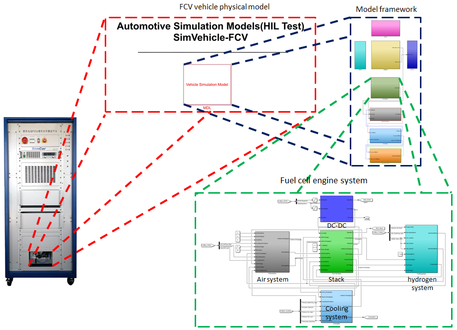
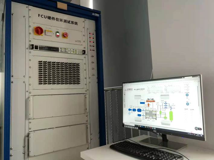
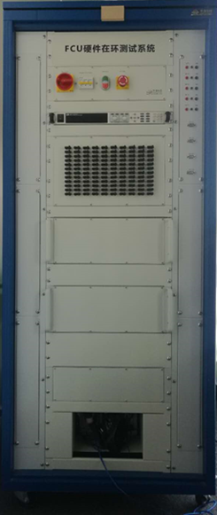
—— FCU Hardware-in-the-loop (HIL) Test System
The FCU HIL test platform can test the functions of FCU controller in all aspects, including functional logic test, fault test, extreme condition test, etc. The testing process can also be managed efficiently, and can generate the test report quickly. It can effectively reduce the times of bench test and road test of FCU controller, shorten the time of product development and reduce the cost of product development.
—— Main Functions
• Test the power off/on control logic of the controller
• Control test for injector valves, compressor, circulating pump, humidifier and fan
• Flow, pressure, temperature, humidity and other sensor signal acquisition
• Hydrogen flow/pressure closed loop control test
• Oxygen flow/pressure closed loop control test
• Fuel cell output power control test
• Fuel cell thermal management function testing
• FCU control diagnostic function and IO diagnostic function test
• CAN communication function test
• Control strategy development and validation
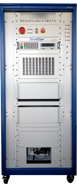
—— System Composition
• Power distribution unit
• Programmable power supply
• BOB
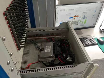
• Controller box
• Signal conditioning unit
• Real-time processor and IO boards
• Real-time simulation model
• Host computer and test management software
• Optional network test equipment
• Fault injection and load simulation unit
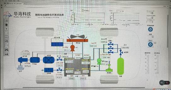
—— Simulation Model
The vehicle model is built based on Matlab/Simulink. All the modules are open source, and users can replace the original modules with their own customized modules. For the fuel cell model, it can simulate various physical characteristics of the fuel cell according to different operating parameters and conditions, and each module can also support the import of experimental data to ensure that its characteristics are consistent with the characteristics of real components.
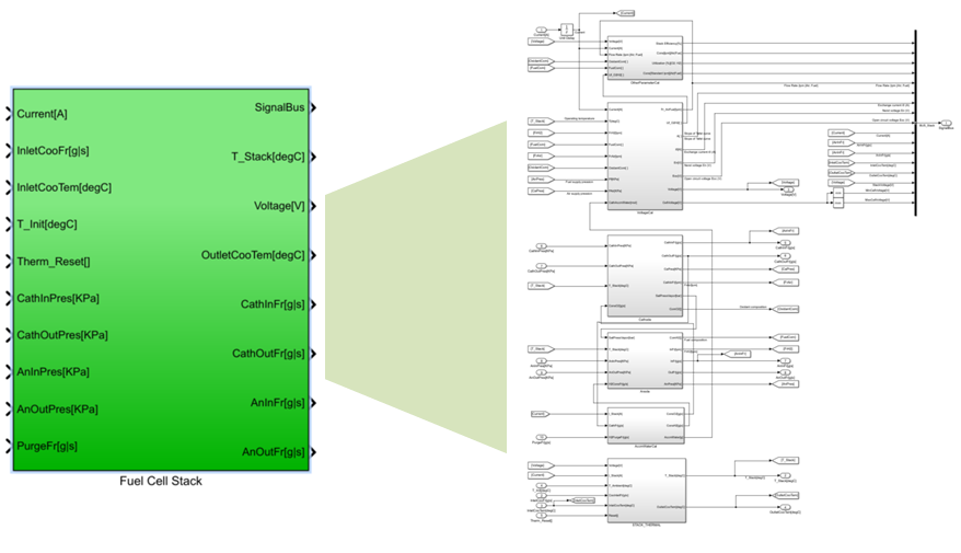
♦ Stack
The stack is built based on thermodynamics and electrochemistry, and the effects of activation polarization, ohmic polarization and concentration polarization of the fuel cell are considered. The voltage, temperature, gas utilization and other parameters of the stack can be calculated according to the changes of current, reaction flow and pressure.
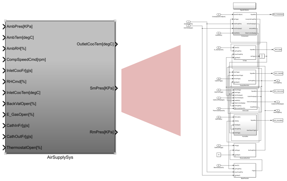
♦ Air supply system
The main function of the air supply system is to clean air, transport air, air pressurization and air humidifying. It is composed of air compressor, intercooler, humidifier, back pressure valve, etc.
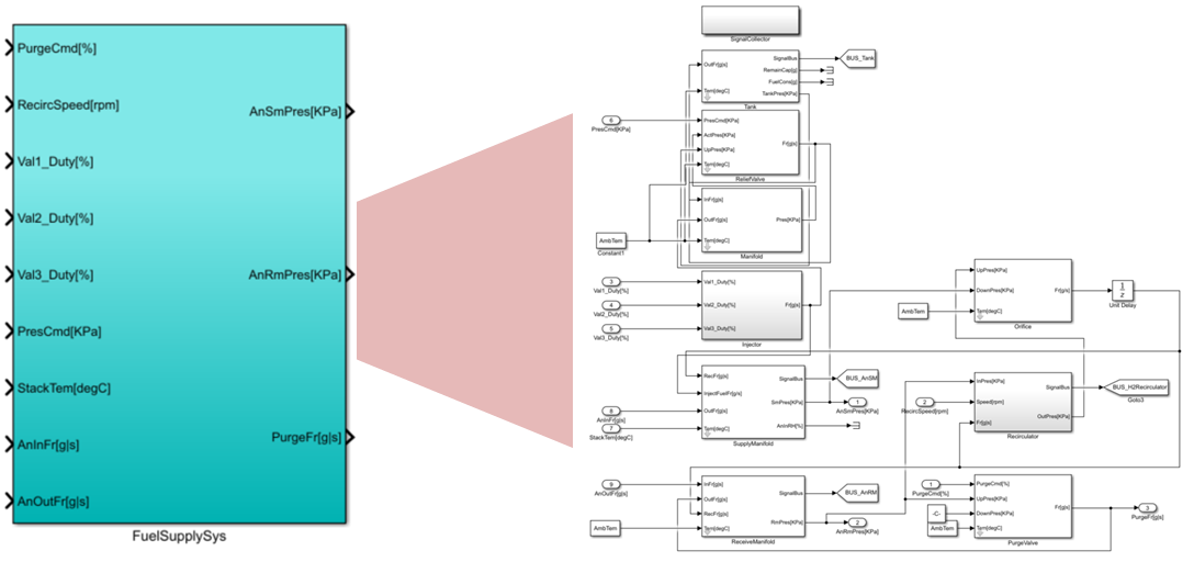
♦ Hydrogen supply system
The main function of the hydrogen supply system is to provide hydrogen with a certain pressure and flow rate, and remove impurities, so that the reaction can goes on normally. It is composed of hydrogen injector, hydrogen circulating pump, hydrogen tank, hydrogen purge valve and so on.
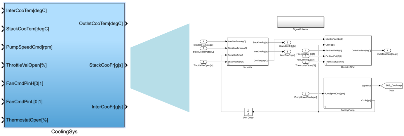
♦ Cooling system
The function of the cooling system is to dissipate the heat generated by the electrochemical reaction of the fuel cell in time, so that the stack can work on the best operating temperature.
The cooling system consists of pump, radiator, fan, etc.
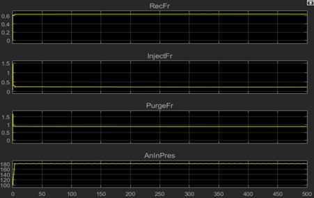
—— Simulation Results
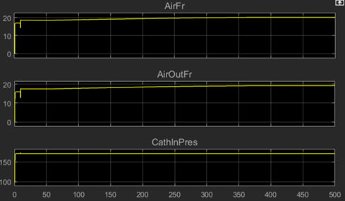
Air system |
Hydrogen system
|
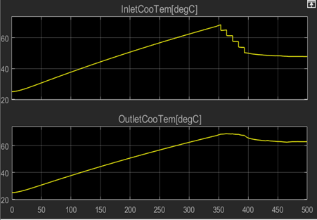
Coolant temperature
|
|
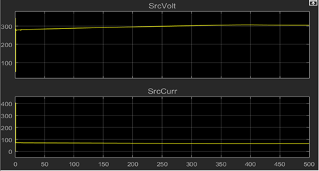
Voltage and current of the stack
|
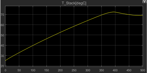
Electric reactor temperature |
—— HIL Test Display
—— Cases
|